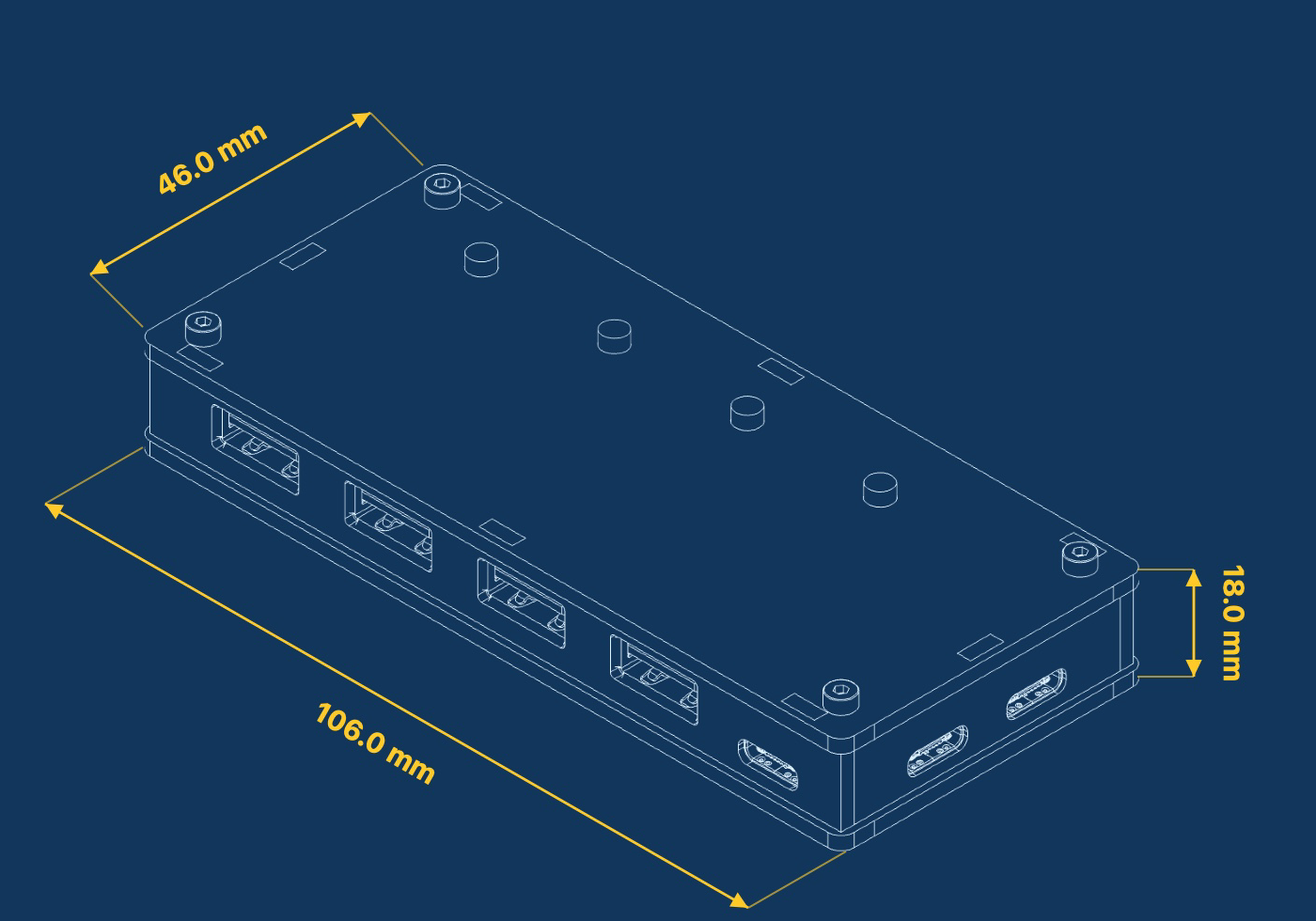
SmartUSBHub Pro 4CH USB2.0 Technical Specifications
Note
The 4CH model supports per-channel voltage/current measurement streaming at up to 100 Hz. The achievable rate depends on the host and software configuration.
Document item |
Details |
|---|---|
Applicable product |
SmartUSBHub Pro 4CH USB2.0 |
Order codes |
|
Document version |
v1.0 |
Release date |
2026-07-23 |
1 Product Overview
SmartUSBHub Pro 4CH USB2.0 is a four-port programmable USB 2.0 High-Speed hub. It independently controls VBUS and USB 2.0 D+ / D- on every downstream port and measures each channel’s VBUS voltage and output current. It is designed for R&D debugging, automated testing, production validation and remote USB device management.
1.1 Model Differences
Variant |
Order code |
Voltage/current measurement |
Included power supply |
|---|---|---|---|
Standard |
|
Yes |
Not included |
Power-adapter bundle |
|
Yes |
5 V / 2 A |
1.2 Key Features
Four USB-A downstream ports with independent VBUS and D+ / D- control.
USB 2.0 High-Speed link rate up to 480 Mbps; compatible with Full-Speed, Low-Speed and USB 1.1 devices.
MTT architecture with an independent transaction translator for each downstream port.
Independent VBUS voltage and output-current measurement on every channel.
USB BC 1.2 CDP support with up to 1.5 A charging current per port; QC, USB PD and other fast-charging protocols are not supported.
Normal mode, interlock mode, configurable power-on defaults and state restoration after power loss.
Four local channel-control buttons.
2 System Architecture
2.1 System Block Diagram

The DATA port carries USB traffic between downstream devices and the host. The CMD port enumerates as a USB CDC serial interface and receives control commands. DATA, CMD and AUX POWER can all feed the internal 5 V rail.
2.2 Interfaces and Indicators
Interface or component |
Quantity |
Function |
|---|---|---|
USB-C DATA |
1 |
Connects to the USB host and carries downstream-device data |
USB-C CMD |
1 |
Connects to the control host and provides the USB CDC command interface |
USB-C AUX POWER |
1 |
Accepts a protected external 5 V DC supply |
USB-A downstream ports |
4 |
Connect controlled USB devices |
Channel buttons |
4 |
Control the corresponding channels |
Status indicator |
1 |
Indicates device operation and command processing |
Channel indicators |
4 |
Indicate the VBUS state of the corresponding channels |
3 Functional Specifications
3.1 USB Data Path
Parameter |
Specification |
|---|---|
USB standard |
USB 2.0 High-Speed |
Maximum link rate |
480 Mbps |
Compatible speeds |
Full-Speed 12 Mbps, Low-Speed 1.5 Mbps, USB 1.1 |
Upstream data port |
1 × USB-C |
Downstream ports |
4 × USB-A |
Hub architecture |
MTT, independent TT for every downstream port |
3.2 Channel Control
Parameter |
Specification |
|---|---|
Channel numbers |
CH1–CH4 |
VBUS control |
Independent on every downstream port |
D+ / D- control |
Independent on every downstream port |
Power/data relationship |
USB data can be disconnected while VBUS remains powered |
Batch control |
Supported |
Normal mode |
Supported |
Interlock mode |
Supported; only one channel can be enabled at a time |
Power-on default state |
Configurable |
State restoration after power loss |
Configurable |
3.3 Charging and Output Path
Parameter |
Specification |
|---|---|
Charging protocol |
USB BC 1.2 CDP |
BC 1.2 charging current |
Up to 1.5 A per port |
Per-channel output-path capability |
Up to 4 A; this is not a guaranteed charging current |
Other fast-charging protocols |
QC, USB PD and other fast-charging protocols are not supported |
3.4 Voltage and Current Measurement
Measurement |
Range |
Resolution |
Accuracy |
|---|---|---|---|
VBUS voltage |
0–5.5 V per channel |
1.48 mV |
±(0.91% × reading + 36 mV) |
Output current |
0–4.0 A per channel |
1.15 mA |
±(2.5% × reading + 50 mA) |
4 Electrical Specifications
Warning: input overvoltage can cause overheating or fire
Only connect a regulated 5 V DC supply to any power input. No input may exceed 5.5 V. Never use a PD trigger, boost cable or other method to apply 9 V, 12 V, 15 V or 20 V to AUX POWER.
Parameter |
Minimum |
Typical |
Maximum |
Unit |
Notes |
|---|---|---|---|---|---|
5 V input voltage |
4.75 |
5.00 |
5.25 |
V |
Recommended operating range |
Absolute maximum input |
0 |
- |
5.5 |
V |
Applies to all power inputs |
Downstream-port VBUS |
4.5 |
5.0 |
5.5 |
V |
Without overload |
Total input current |
- |
- |
<10 |
A |
Sum of DATA, CMD and AUX POWER currents |
Per-channel output-path capability |
- |
- |
4 |
A |
Does not represent charging-protocol current |
Included adapter output |
- |
2 |
- |
A |
Shared by all four ports |
Important: size the power supply for the actual load
If four devices each draw the USB BC 1.2 CDP maximum of 1.5 A, the theoretical load is approximately 5 V / 6 A. The combined capacity of the three power inputs must cover the actual load, and total input current must remain below 10 A.
5 Protection and Safety Limits
Item |
Specification |
|---|---|
DATA and CMD power paths |
Reverse-current, overvoltage and overcurrent protection |
Downstream ports |
Resettable fuse on every port |
AUX POWER |
No independent onboard overcurrent protection; the external supply must provide current limiting and short-circuit protection |
Input voltage |
Regulated 5 V DC only; 5.5 V absolute maximum |
The 4 A per-channel rating is the output-path capability, not a guaranteed charging current.
USB BC 1.2 CDP charging current is limited to 1.5 A per port.
Available output current depends on the supply, cables, connectors, ambient temperature and cooling.
Turning off VBUS or D+ / D- is equivalent to unplugging a device. Stop file writes, firmware updates and other non-interruptible operations first.
6 Mechanical and Environmental Specifications
Parameter |
Specification |
|---|---|
Dimensions |
106 mm × 46 mm × 18 mm |
Device weight |
52 g |
Enclosure material |
PMMA |
Mounting |
Supports stacked mounting with standoffs |
Operating temperature |
0–50 °C, non-condensing |
Storage temperature |
-10–85 °C, non-condensing |